Q1 : Which of the following is not a primary function of the pump casing?
- a. Transmit torque from the driver to the impeller
- b. To convert kinetic energy into pressure energy
- c. To develop dynamic head
- d. Directing flow into and out of impeller
- e. Provide support to the bearing bracket
- f. Incorporate nozzles to connect suction & discharge piping.
Answer :
- a. Transmit torque from the driver to the impeller
- c. To develop dynamic head
Description :
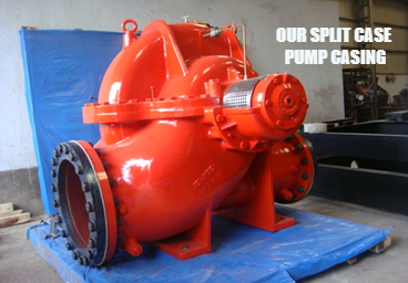
The main functions of the pump casing Includes:
- To convert kinetic energy into pressure energy with minimum hydraulic losses by means of volute, diffusers or guide.
- Incorporates nozzles to connect suction & discharge piping and directs flow into & out of the impeller.
- Provides support to bearing bracket.
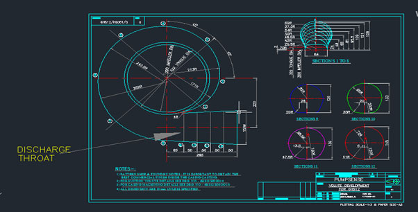
- Volute casing mainly provides uniform velocity distribution up to the discharge throat, (as it conforms less net radial thrust) and within the discharge nozzle kinetic energy is converted into pressure energy.
N.B – DYNAMIC HEAD IS ONLY DEVLOPED BY THE IMPELLER
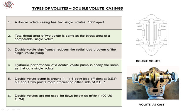
Pump casings can be of various geometric profiles, such as, Volute (single & double) or Concentric.
Q2 : A pump develops 100 m head while handling kerosene with specific gravity of 0.8. What head will the pump develop if the liquid handled is water:
- a. 120m
- b. 100m
- c. 80m
- d. 60m
Answer :
- c. 80m
Description :
We know that developed pressure is, P = ρ.g.H
Where ρ is density of fluid, and H is head of fluid column
So, Pressure developed by the pump handling kerosene = Pressure developed by the pump handling water
Or, ρkerosense . g . Hkerosene = ρwater . g . Hwater
Or, Head of water column = (ρkerosense . Hkerosene) / ρwater
Or, Head of water column = (100*0.8*1000)/ (1000) = 80m
Q3 : A pump lifts water from a sump. Static height of the pump center line from the water level in the sump is 5m. Friction loss in the suction pipe line 0.5m, vapor pressure at pumping temperature is 0.5m and the atmospheric pressure is 10.3m of water column. What is the approximate NPSH available at this installation?
- a. 14.3 m
- b. 4.3 m
- c. 4.8 m
- d. 14.8 m
Answer :
- b. 4.3 m
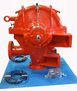
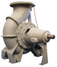
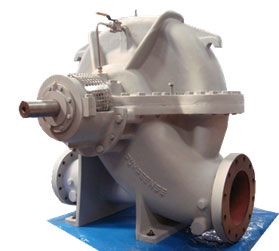
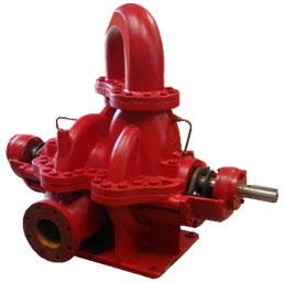
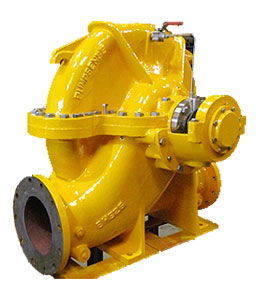
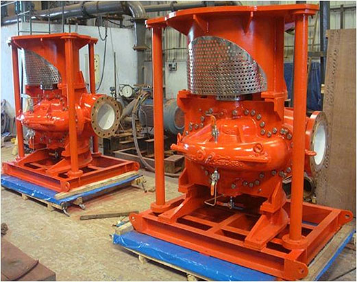
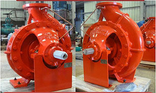
10″x12″-13″ Size chilled water supply pump supplied to Australia
Description :
Vapour pressure head (hvap) = 0.5 m
Atmospheric pressure head (ha) = 10.3 m water column.
Gauge pressure reading at suction vessel (Pg) = 0 so hg = 0 m
The frictional head loss (hf) in piping is 0.5 m
The suction lift (hss) = 5.0 m
NPSH available
= ha + hg – hss – hf – hvap
= (10.3 + 0 – 5 – 0.5 – 0.5) m
= 4.3 m
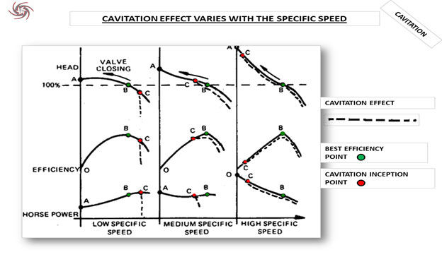
Q4 : Which of the following statements about cavitation is not true?
- a. Cavitation occurs when NPSH available is less than the NPSH required by the pump.
- b. Cavitation is caused by the collapse of air bubbles in the suction side of the pump.
- c. Cavitation does not occur during part flow operation since available NPSH is high.
- d. Cavitation occurs only on the suction side of the impellers.
- e. Cast Iron impellers have the least ability to resist cavitation damage.
Answer :
- b. Cavitation is caused by the collapse of air bubbles in the suction side of the pump.
- c. Cavitation does not occur during part flow operation since available NPSH is high.
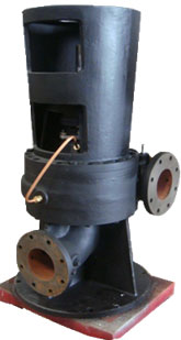
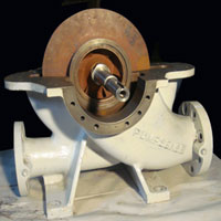
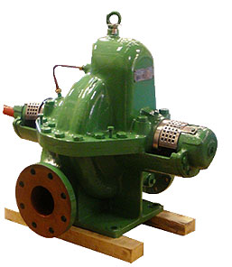
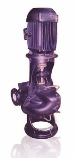
FPSO Vertical fire water pump 10″x12″x25″ in ductile NiResist. Specila construction to ensure vibration free operation
Description :
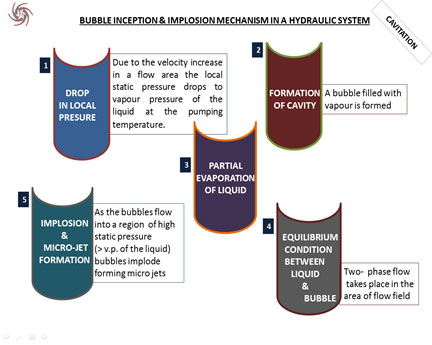
Cavitation mainly occurs on the suction side of the pump at the inlet portion of the impeller. However, cavitation damages may also occur on discharge vane tips & volute tongues on the delivery side of the pump.
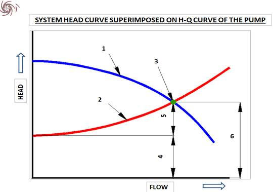
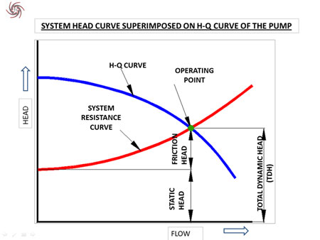
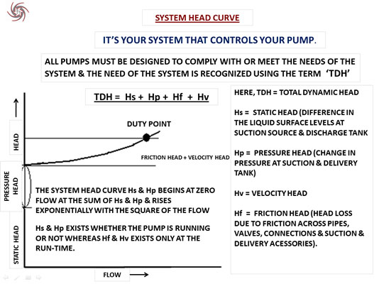
Q5 : The following diagram shows pump performance curve superimposed on system characteristics. Can you identify the various terms in the table?
| Description | No. |
|---|---|
| a. System Resistance Curve | |
| b. Friction Head | |
| c. Static Head | |
| d. Total Dynamic Head | |
| e. Head Capacity Curve | |
| f. Operating Point |
- A. (a) - 2 (b) - 5 (c) - 4 (d) - 6 (e) - 1 (f) - 3
- B. (a) - 1 (b) - 4 (c) - 6 (d) - 5 (e) - 2 (f) - 3
- C. (a) - 2 (b) - 6 (c) - 4 (d) - 5 (e) - 1 (f) - 3
- D. (a) - 1 (b) - 4 (c) - 5 (d) - 6 (e) - 2 (f) - 3
Answer :
- A. (a) - 2 (b) - 5 (c) - 4 (d) - 6 (e) - 1 (f) - 3
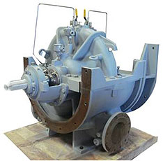
ESL 350x300-400 for air-conditioning application in an airport in China
Description :
| Description | No. |
|---|---|
| a. System Resistance Curve | 2 |
| b. Friction Head | 5 |
| c. Static Head | 4 |
| d. Total Dynamic Head | 6 |
| e. Head Capacity Curve | 1 |
| f. Operating Point | 3 |
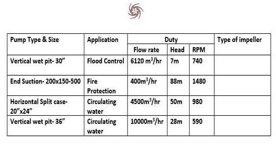
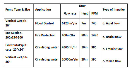
Q6 : For each of the following duties which is the most appropriate type of impeller:
- a. Radial flow
- b. Francis Vane
- c. Mixed Flow
- d. Axial Flow
- 1. c - b - a - d
- 2. a - d - b - c
- 3. d - a - b - c
- 4. b - a - d - c
Answer :
- 3. d - a - b - c
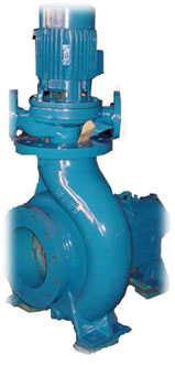
Our Compact Split Case Pump High Pressure Application Ductile Iron Casing
Description :
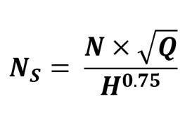
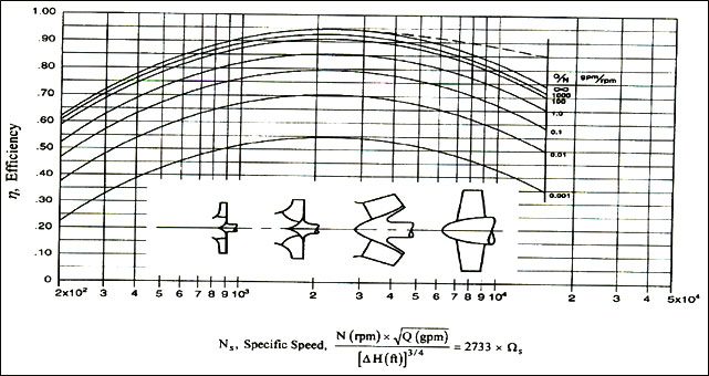
The most important criteria for predicting the type of flow through an impeller is to determine the Specific Speed of the pump. Specific speed is a design index used to determine the impeller type. Mathematically,
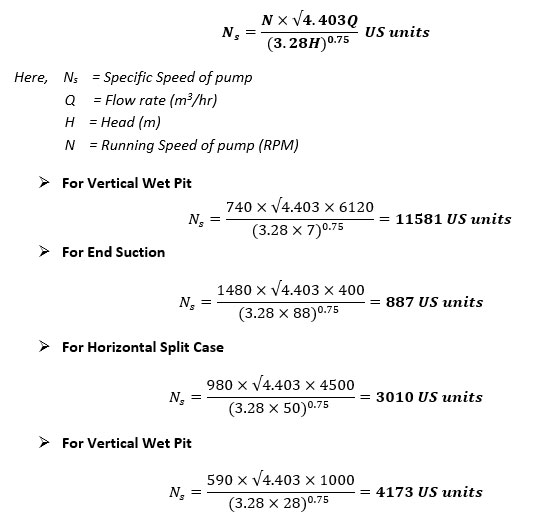
To relate the range of Specific Speed with the type of Impeller/flow, we may consult the following chart for reference.

Q7 : In a pumping system where the major component of the total head is friction, which of the following three methods of flow control is the most energy efficient? The flow through a pump can be controlled by:
- a) Throttling
- b) Connecting or disconnecting pump running in series or parallel
- c) Speed control
Answer :
- c) Speed control
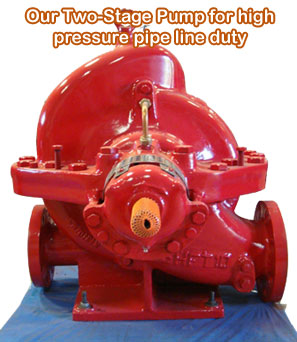
Our Two-Stage Pump For High Pressure Pipe Line Duty
Description :
Q8 : Which of the following properties are important for selecting the material of construction of an impeller:
- a) Endurance Limit
- b) Corrosion Resistance
- c) Abrasive Wear Resistance
- d) Cavitation Resistance
- e) Casting and machining properties
- f) Tip speed
- g) Cost
- h) Working Pressure
- i) Galling Characteristics
Answer :
- (b) Corrosion Resistance
- (c) Abrasive Wear Resistance
- (d) Cavitation Resistance
- (e) Casting and machining properties
- (f) Tip speed
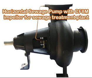
Horizontal Sewage Pump With CF8M Impeller For Sewage Treatment Plant
Description :
Q9 : According to American Standard NFPA20 for fire pumps, pumps are generally provided with gland packing and mechanical seals are not used. What is the main reason for using gland packing in place of mechanical seals for these pumps?
- a) Gland Packing is easily installed.
- b) Gland Packing is cheaper than mechanical seal.
- c) Leakage tends to increase gradually giving early indication of impending failure.
- d) Gland Packing is less sensitive to the axial movement of shaft compared to mechanical seal.
- e) Gland Packing is easily replaced when the gland is split.
Answer :
- c) Leakage tends to increase gradually giving early indication of impending failure.
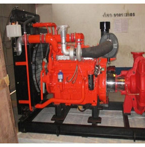
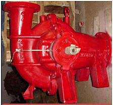
1250 GPM Fire Pump for 200m & higher heads supplied by us
Description :
Q10 : The following is a list of some of the Quality Assurance checks carried out by a pump manufacturer:
- a) Shaft Ultrasonic test
- b) Casing UTS, hardness test, chemical test
- c) Impeller - chemical analysis
- d) Impeller – dynamic balancing
- e) Casing - hydrostatic pressure test
- f) Pump - Performance test
- g) Pump - dimensional check
- h) NPSH test
The following is a list of the Test Reports as required by a user:
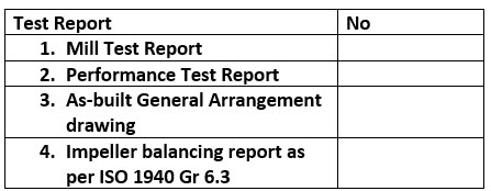
Please identify the QA document which contains the appropriate test report from the following options:
A. 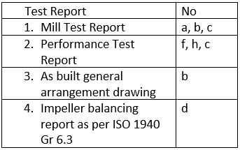 |
B. 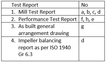 |
C. 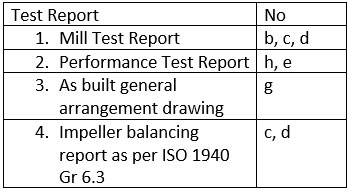 |
D. 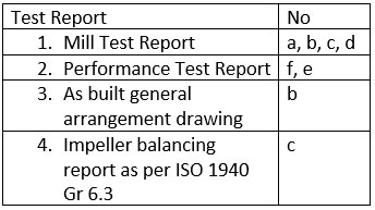 |
Answer :
- B.
4′ x 4′ Small Range Vertical Sewage Pump
Description :
Q11 : Which of the following impeller types has the highest efficiency potential?
- a) Radial flow impeller
- b) Francis Vane impeller
- c) Mixed flow impeller
- d) Axial flow impeller
Answer :
- b) Francis Vane impeller
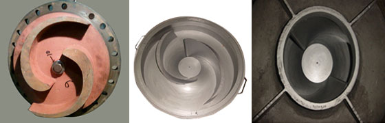
Different types of Impellers developed by our Team at Pumpsense
Description :
Different types of Impellers are designed and used as we require a huge range of operation for pumps, in general, which cannot be satisfied with a single type. The type of Impeller to be used in a particular application depends on the duty point, according to which various types of Impellers are designated.
Duty point refers to the (1) flow rate and (2) head required to be supplied by the pump at (3) a given running speed. For the purpose of design, a design index has been defined called the Specific Speed of the pump. This incorporates the three important parameters of duty point to yield a single design index to ascertain the type of Impeller required for a particular application.
Mathematically, Specific Speed is defined as:
Different types of Impellers according to Specific Speed:
- (1) Radial Flow : When the flow rate is low and the head is high, this type is used. Specific Speed ranges from 500-1700. The fluid enters the Impeller in axial direction and quickly changes to radial direction at the outlet.
- (2) Francis Vane : When the flow rate is low and the head is high, this type is used. Specific Speed ranges from 1700-4000. The fluid enters the impeller in axial direction. Only difference from radial flow impellers is that the fluid changes to radial direction at outlet in a more gradual manner. This smooth transition gives Francis Vanes the highest efficiency.
- (3) Mixed Flow : When the flow rate is high and the head is moderate, this type is used. Specific Speed ranges from 4000-9000. The fluid enters the impeller in axial direction and leaves obliquely making an angle with the radial & axial directions.
- (4) Axial Flow (Propeller) : When the flow rate is high and the head is low, this type is used. Specific Speed is above 9000. The fluid enters the impeller in axial direction and leaves in axial direction too.
So, Specific speed is largely related to the discharge angle, relative to the inlet. This, in effect, determines the smoothness of flow transition inside the impeller, which, in turn, determines efficiency.
Q12 : The following are four End Suction ISO 2858 pumps. Pump efficiencies are
- 1. 72%
- 2. 75%
- 3. 81%
- 4. 83%
Can you place the correct efficiencies in the appropriate boxes?
| Pump Size | Best efficiency duty point at 1480 rpm | Efficiency |
|---|---|---|
| A. 125x80-400 | 140 m3/hr, 50m | |
| B. 125x100-400 | 190 m3/hr, 50m | |
| C. 150x125-400 | 300 m3/hr, 50m | |
| D. 200x150-400 | 450 m3/hr, 50m |
- a) A-1 B-2 C-3 D-4
- b) A-4 B-3 C-2 D-1
- c) A-3 B-1 C-2 D-4
- d) A-2 B-4 C-3 D-1
All the pumps generate the same head and impeller diameters are identical (400mm) - Why are the efficiencies different?
Answer :
- a) A-1 B-2 C-3 D-4
ISO 2858 End Suction Pump 250x200-315 used for air conditionong applications
Description :
The efficiency of the models are as follows:
| Pump Size | Best efficiency duty point at 1480 rpm | Efficiency |
|---|---|---|
| 125x80-400 | 140 m3/hr, 50m | 72% |
| 125x100-400 | 190 m3/hr, 50m | 75% |
| 150x125-400 | 300 m3/hr, 50m | 81% |
| 200x150-400 | 450 m3/hr, 50m | 83% |
The Specific Speed & Flow-rate to running speed ratio is calculated to compare with standard chart:
| Pump Size | Best efficiency duty point at 1480 rpm | Sp speed | Q/N (gpm/rpm) |
|---|---|---|---|
| 125x80-400 | 140 m3/hr, 50m | 801 | 0.4165 |
| 125x100-400 | 190 m3/hr, 50m | 933 | 0.56525 |
| 150x125-400 | 300 m3/hr, 50m | 1173 | 0.8925 |
| 200x150-400 | 450 m3/hr, 50m | 1437 | 1.33875 |
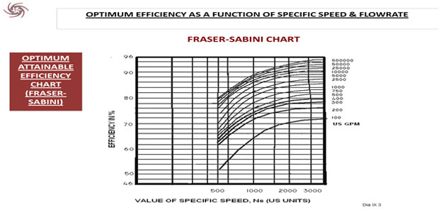
The above efficiencies can be predicted by consulting the following chart. As a general rule, given two pumps of same specific speed, the one with higher flow rate will give higher efficiency.
Efficiency as a function of specific speed and (flowrate/rpm)- Hydraulic Institute Standard
Q13 : Select the Pumps for the given duty points:
| S/N | SPEED (RPM) | HEAD (m) | FLOW (Litre Per Sec) |
|---|---|---|---|
| 1 | 1480 | 20 | 100 LPS |
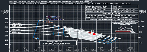
| 2 | 1480 | 22 | 140 LPS |
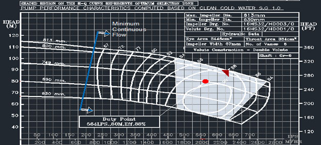
| 3 | 1000 | 80 | 564 LPS |
| 4 | 1480 | 100 | 564 LPS |
- a) 1:6HS14 2:8HS10 3:16HS32 4:12HS23
- b) 1:8HS12 2:8HS12 3:14HS32 4:14HS26
- c) 1:6HS12 2:8HS12 3:16HS32 4:12HS23
- d) 1:6HS10 2:10HS12 3:18HS25 4:10HS22
Answer :
- c) 1:6HS12 2:8HS12 3:16HS32 4:12HS23
Compact Split Case Ship’s Fire Pump used for Firefighting Application
Description :
FIRST PUMP
Head - 20m, Flow - 100LPS = 360 M3/HR
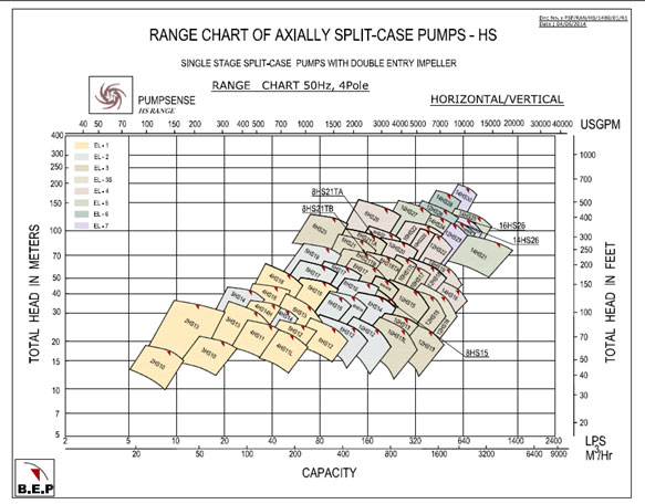
First we have to select a pump from range chart.
A range chart depends on several parameters. First you have to fix these parameters, to select appropriate range chart.
| Parameter Name | Available Type | Selection Criterion | Selected Functions |
|---|---|---|---|
| 1. PUMP TYPE | CSC, EMF, ES, ESL, HS, HST, SEWS etc. | Every pump has its own benefits and limitation and specific operation conditions and suitability. BASIC functions are preference, available NPSHA, overall SIZE, pumping fluid conditions. | As here, NPSHA, suction condition, size etc. are not mentioned, we choose HS range |
| 2. MOTOR TYPE |
2 pole 50hz, 3000rpm 4 pole 50Hz, 1500rpm 4 pole 60Hz, 1800rpm 6 pole 50Hz, 1000rpm 6 pole 60Hz, 1200rpm 8 pole 50Hz, 750rpm 8 pole 60Hz, 900rpm |
RPM= 120f/P f= frequency P= no of pole Here, RPM=1480 Which is nearly 1500. And taking f= 50Hz, we have p=4. |
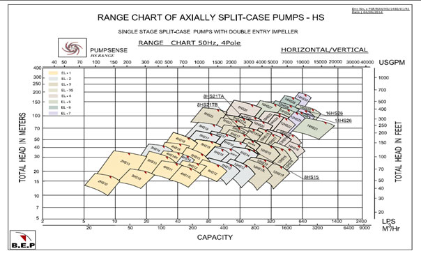
From this range chart, it is obvious that either 6HS12 OR 8HS12 is suitable for this job.
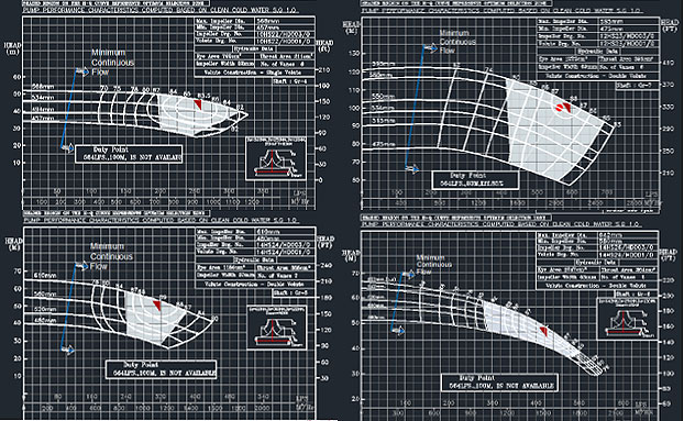
Next step is to go through the performance curves of these two pumps.
PERFORMANCE CURVE OF 8HS12
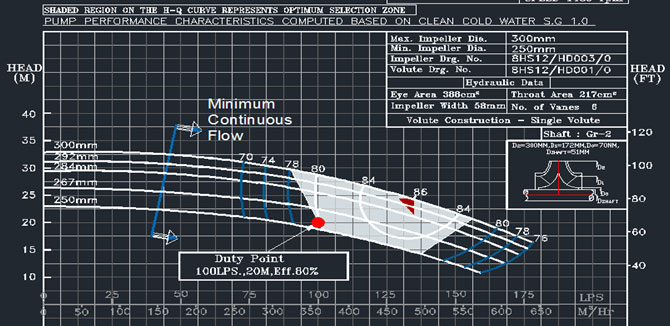
As we can see, the duty point is almost out of its Allowable Operating Zone, so we check the performance curve of 6HS12
PERFORMANCE CURVE OF 6HS12
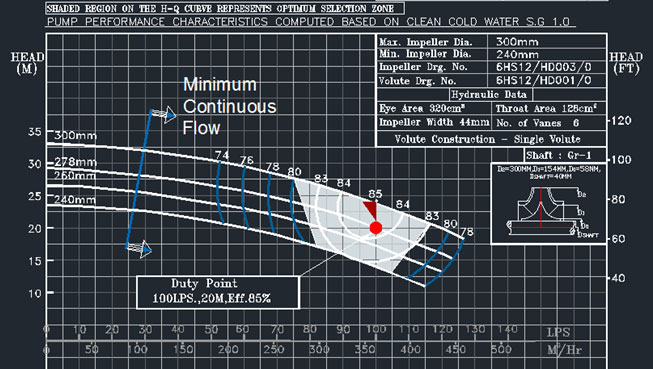
So, it is obvious that 6HS12 is the most suitable pump for this given duty.
SECOND PUMP
From the range chart, we select 8HS12 and verify it with its performance curve.
PERFORMANCE CURVE OF 8HS12
THIRD PUMP
Pump type = same
Motor type = 6 pole 50hz
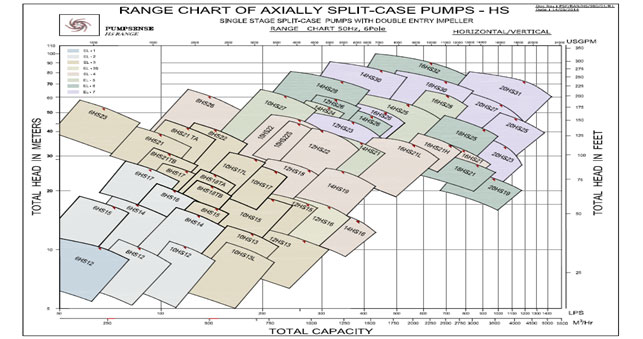
16HS32 is the available option.
PERFORMANCE CURVE OF 16HS32
FOURTH PUMP
Here only RPM has changed, so motor type will be 4 pole 50 hz 1500 rpm.
Possible pumps are 14HS26, 12HS23, 10HS22, 14HS24
PERFORMANCE CURVE OF 14HS26, 12HS23, 10HS22, 14HS24
So the 4th pump will be 12HS23.
Q14 : You have two pumps conforming to ISO 2858 standard one from Europe (KSB) and the other from Australia (TKL). Both have the same designation - 100x80-315 and both run at 1500 rpm. You would expect both the pumps to have:
- a) Same design capacity, head and impeller diameter
- b) Identical foot-print and installation interface dimensions
- c) Same materials of construction
- d) None of the above
Answer :
- a) Same design capacity, head and impeller diameter
- b) Identical foot-print and installation interface dimensions
- c) Same materials of construction
Our ESL 400x400-450 supplied for an industrial cooling water application in West Africa.
Description :
Example of a pump brochure as per ISO 2858.
Q15 : American Petroleum Institute Standard API 610 (10th edition) is a process pump standard for petrochemical plants and refineries. A user will insist on pumps complying to this standard when which of the following is required?
- a) Optimum pump efficiency is wanted
- b) Lowest life cycle cost for the installation
- c) Highest reliability in a critical application
- d) Lowest environmental impact
Answer :
- c) Highest reliability in a critical application
High speed mine dewatering pump- 8′x10′-26′. Double Volute Construction. Twenty units supplied to Atlas Mining in Philippines.
Description :
API pumps ensure highest reliability and to do so it uses large bearings and advanced sealing system which consumes more energy. Though it ensures safe operating conditions the power consumption in API pumping system is high. So, it has moderate environmental impact with high life cycle cost and also power consumption is more, so efficiency is not optimum.
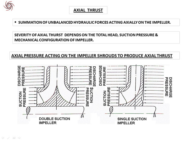
Q16 : A double suction split-case pump is sometimes preferred over an end suction pump because of?
- a) Smaller installation dimensions
- b) Ease of maintenance
- c) Absence of radial thrust load
- d) All of the above
Answer :
- b) Ease of maintenance
Our CSC range: Large shaft and low shaft span
Description :
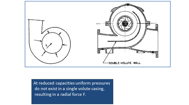
Q17 : There are two identical end suction pumps A and B of designation 200x150-500. Both A and B have identical impellers and shafts, the only difference between these two pumps being that A has a single volute casing while B uses a double volute casing. Which of the following statements is true?
- a) B is likely to be more efficient than A at the best efficiency point (design point)
- b) Shaft deflection at the stuffing box will be higher for B
- c) A will have lower axial thrust load
- d) B will have lower radial thrust load at part flow operation
Answer :
- d) B will have lower radial thrust load at part flow operation
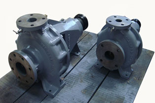
Two ISO 2858 End Suction Pumps Supplied in Ductile Ni Resist Construction for sea water application to an Australia
Description :
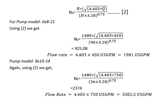
Q18 : There are two axially split-case pumps with the following description:
| Parameters | Pump model- 6x8-21 | Pump model- 8x10-14 |
|---|---|---|
| Rated capacity | 450 m3/hr. | 750 m3/hr. |
| Rated head | 90 m | 36 m |
| Impeller diameter | 540 mm | 360 mm |
| Impeller width at outlet (including shrouds) | 40 mm | 76 mm |
| Speed | 1480 rpm | 1480 rpm |
| Type of casing | Single volute | Single volute |
| Type of impeller | Double entry | Double entry |
Which of the following statements is true?
- a) Axial thrust of 8x10-14 is likely to be greater than that of 6x8-21
- b) 6x8-21 is likely to be more efficient than 8x10-14
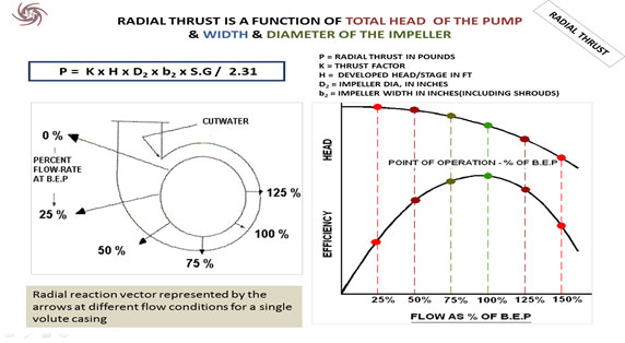
- c) Radial thrust at 50% flow will be more in case of 6x8-21
- d) None of the above
Answer :
- c) Radial thrust at 50% flow will be more in case of 6x8-21
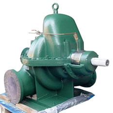
27 Nos. of Vertical 8′×10′-26′ Mars Tanker Cargo Pumps were supplied to UK Navy
Description :
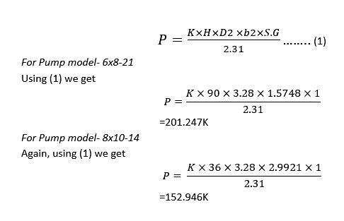
So, option (c) is right
In double entry impeller the axial thrust is almost negligible.
So, option (A) is invalid.

By the curve and calculated data from equation 2 we have,
Optimum efficiency of pump 6x8-21 nearly 82%
Optimum efficiency of pump 8x10-14 nearly 86%
8x10-14 is likely to be more efficient than 6x8-21
So, option (B) is wrong
Q19 : Which of the following statement is not true for a two stage axially split-case pump with two back-to-back single-entry impellers?
- a) Protect the shaft from abrasion and wear
- b) Increase the stiffness of the rotating element (shaft to be more precise)
- c) Reduce leakage losses through the stuffing box
- d) None of the above
Answer :
- a) Protect the shaft from abrasion and wear
- b) Increase the stiffness of the rotating element (shaft to be more precise)

Our Sewage Pump used for solid handling application
Description :
The functions of a shaft sleeve are the following:

Note-Leakage is prevented by the use of Gland Packing/ Mechanical Seal
Q20 : Which of the following statement is not true for a two stage axially split-case pump with two back to back single-entry impellers?
- a) Total head developed by the pump is the sum of heads developed by each stage.
- b) The pump axial thrust is balanced because of two opposed single-entry impellers.
- c) The pump radial thrust is balanced because the volutes of two stages are at 1800 to each other.
- d) The total capacity of the pump is the sum of the flow through each stage.
Answer :
- d) The total capacity of the pump is the sum of the flow through each stage.
Our 10′x12′-22′ two stage pump supplied for mine dewatering duty to Australia
Description :
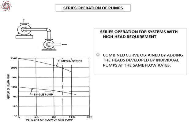
In a two-stage pump, the working fluid passes through the first stage impeller leading to a rise in pressure. This pressurized fluid then enters the second stage impeller for subsequent rise in pressure. This is equivalent to two pumps working in series with each other. Thus, the following discussion about series operation is applicable for multi-stage pumps too.
Q21 : Which of the following statement is not true for a two stage axially split-case pump with two back to back single-entry impellers?
- a) Total head developed by the pump is the sum of heads developed by each stage.
- b) The pump axial thrust is balanced because of two opposed single-entry impellers.
- c) The pump radial thrust is balanced because the volutes of two stages are at 1800 to each other.
- d) The total capacity of the pump is the sum of the flow through each stage.
Answer :
- c) The pump radial thrust is balanced because the volutes of two stages are at 1800 to each other.
Our Double stage, double entry packed gland fire pump
Description :
In gland packing application , fluid leakage is mandatory as the leaked fluid act as a lubricating agent, which reduces the friction losses and at the same time cools the package temperature. Now, if the leakage is reduced to zero by tightening the split glands, this increases the friction and heats up the packing and as a result burns the packing. So a control leakage is necessary for sound operation of the pump. Gland packing is also known as a soft type packing. Leakage from gland packing also helps us to know about the impending failure depending on the amount of fluid leaking from it.
Q22 : Which of the following statements about pump shaft is not true?
- a) Diameter of the pump shaft depends mainly on the power absorbed (kW), speed of the pump and the permissible shear stress for the shaft material selected.
- b) Shaft stiffness factor (L3/D4) where L is the bearing span and D is the average shaft diameter is one of the measures of the shaft deflection.
- c) Keyways, threads and sharp changes of section are stress raisers in a pump shaft.
- d) A double volute pump needs shaft of larger diameter compared to a single volute pump.
Answer :
- c) Keyways, threads and sharp changes of section are stress raisers in a pump shaft.
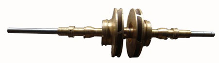
Shaft of a double stage pump
Description :
The shaft primarily takes the radial load applied by the fluid on the pump. In a double volute casing radial thrust is very less, so the necessity of a shaft with large diameter is not required.
Q23 : Which of the following statements about pump casings is not true?
- a) Pump casing plays an important role in the generation of dynamic head, same as the pump impeller.
- b) Thickness of the pump casing depends on the yield strength of the material used, permissible deflection, corrosion allowance required and the maximum test pressure.
- c) Single volute casing is easier to cast compared to a double volute casing.
- d) Casings are vulnerable to leakage, during pressure test, in areas where there are sharp changes of section.
Answer :
- a) Pump casing plays an important role in the generation of dynamic head, same as the pump impeller.
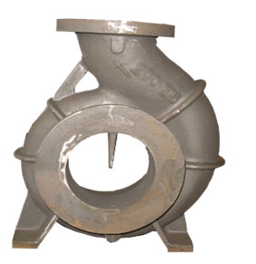
All Bronze Casing of End Suction Model
Description :
Function of casing
- • To convert kinetic energy into pressure energy with minimum hydraulic losses by means of volute, diffusers or guide.
- • Incorporates nozzles to connect suction & discharge piping and directs flow into & out of the impeller .
- • Provides support to bearing bracket.
- • Volute casing mainly provides uniform velocity distribution up to the discharge throat, (as it conforms less net radial thrust) and within the discharge nozzle kinetic energy is converted into pressure energy.
N.B: DYNAMIC HEAD IS ONLY DEVLOPED BY THE IMPELLER
Q24 : Euler's equation He = U2VU2 / g assumes infinite no of vanes and radial entry into impeller eye (Vu1 = 0). According to this equation, Euler's head depends on which of the following?
- a) Impeller type, speed and outlet diameter.
- b) Impeller outlet vane angle, speed and outlet diameter.
- c) Impeller inlet and outlet diameter, speed and flow.
- d) None of the above.
Answer :
- b) Impeller outlet vane angle, speed and outlet diameter.
Double Entry Impeller of Splitcase model
Description :
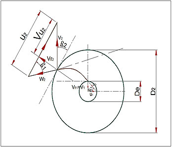
He = U2VU2 / g
Here U2 = ΠD2 N / 60 , so U2 is a function of rpm and outside diameter
And Vu2 = V2cosβ2 so, Vu2 is a function of absolute velocity and outlet angle.
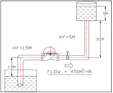
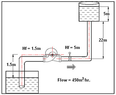
Q25 : For the pumping system shown in the figure below, calculate the total head and the power absorbed by the pump. Assume pump efficiency of 80%.
Power absorbed is given by:
BkW = (Q×H×S.G.) / (3.67×efficiency)
Q – Flow rate in m3/hr
H – Total Dynamic Head in meter water column (m)
S.G – Specific Gravity of the working fluid
- a) 30 m and 46 kW
- b) 32 m and 49 kW
- c) 35 m and 53.6 kW
- d) 30 m and 4.6 kW
Answer :
- c) 35 m and 53.6 kW
Split Case Pump model 8HS26
Description :
H(m) = static lift + sum of total friction losses in suction line + sum of total friction losses in delivery line + delivery head
= 1.5 + 1.5 +5 + 22 + 5 = 35m
BkW = Q×H×S.G. / 3.67×efficiency
= 450×35×1(assuming water) / 3.67×80
= 53.6 Kw
Q26 : A centrifugal pump generates a pressure of 100 psi (a head of 231 ft = 100 psi x 2.31), while handling clean water of specific gravity 1.0. What pressures and head will this pump generate when pumping brine with sp. gr. 1.2 and kerosene with sp. gr. 0.8?
- a) Brine (head = 192.5 ft, pressure = 100 psi) & kerosene (head = 288.7 ft, pressure = 100 psi)
- b) Brine (head = 231 ft, pressure = 83.3 psi) & kerosene (head = 231 ft, pressure = 100 ps)
- c) Brine (head = 231 ft, pressure = 120 psi) & kerosene (head = 231 ft, pressure = 80 psi)
- d) Brine (head = 192.5 ft, pressure = 120 psi) & kerosene (head = 208.7 ft, pressure = 80 psi)
Answer :
- c) Brine (head = 231 ft, pressure = 120 psi) & kerosene (head = 231 ft, pressure = 80 psi)
General purpose two stage pump
Description :
Pump developed head is a system function that is constant. So, the developed head remains same.
Head developed by the pump handling brine = head developed by the pump handling water
Developed Pressure by the pump handling brine / specific gravity of brine = Developed Pressure by the pump handling water / specific gravity of water
Developed Pressure by the pump handling brine = 100 x 1.2 / 1 = 120 psi
In the same way, Developed Pressure by the pump handling kerosene = 80 psi
Q27 : The affinity laws of centrifugal pumps suggest that pump capacity varies directly with the impeller diameter, pump head as the square of the diameter and power as the cube of the diameter (assuming the efficiency is unchanged). The law holds good for impeller trims limited by the pump specific speed, impeller type and inlet diameter of the impeller. Assuming that the affinity laws hold good for the impeller trim shown below, what will be the capacity, head and efficiency for the current operating point?
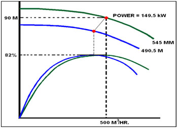
- a) Q = 450 m3/hr., H= 81 m, η = 82% and power = 121 kW
- b) Q = 405 m3/hr., H= 72.9 m, η = 73.8% and power = 109 kW
- c) Q = 450 m3/hr., H= 72.9 m, η = 82% and power = 109 kW
- d) Q = 405 m3/hr., H= 81 m, η = 82% and power = 109 kW
Answer :
- c) Q = 450 m3/hr., H= 72.9 m, η = 82% and power = 109 kW
Single Entry Impeller – End suction pump
Description :
The affinity laws of centrifugal pumps suggest that pump capacity varies directly with the impeller diameter, pump head as the square of the diameter and power as the cube of the diameter (assuming the efficiency is unchanged). So, the efficiency will be 82% (unchanged)
Flow calculation
Q2 = Q1× ( D2 / D1 ) = 500× ( 490.5 / 545 ) = 450 m3/hr
Head calculation
H2 = H1 × ( D2 / D1 )2 = 90× ( 490.5 / 545 )2 = 72.9 m
Power calculation
P2 = P1 × ( D2 / D1 )3 = 149.5× ( 490.5 / 545 )3 = 109 KW
Q28 : A pump manufacturer has to test an external firefighting pump for ship (FiFi pump) of the following specifications:
| Capacity | 2400 m3/hr. |
| Head | 150 m |
| Efficiency | 86% |
| Speed | 1800 rpm |
| Medium | Sea water (sp. gr. = 1.03) |
| Driver | Main propulsion engine through power take-off and gear box |
The manufacturer can test pump at his works, using one of the test motors at six pole speed (1000 rpm synchronous). What will be the rated duty condition of the pump at 1000 rpm at the test bed and what should be the rating of the test- motor. Test bed uses clean cold water (sp. gr. = 1.0) for testing.
- a) Q = 1333 m3/hr., H = 83.3 m, motor = 400 kW, 6 pole
- b) Q = 1333 m3/hr., H = 46.3 m, motor = 230 kW, 6 pole
- c) Q = 740 m3/hr., H = 83.3 m, motor = 215 kW, 6 pole
- d) Q = 740 m3/hr., H = 83.3 m, motor = 215 kW, 6 pole
Answer :
- b) Q = 1333 m3/hr., H = 46.3 m, motor = 230 kW, 6 pole
FiFi pump - 5SF19S with engine
Description :
Q2 = Q1× ( N2 / N1 ) = 2400× ( 1000 / 1800 ) =1333 m3/hr
H2 = H1× ( N2 / N1 ) 2 =150× ( 1000 / 1800 ) 2 =46.2m
BKW1 = ( Q(m3/hr)×H(m)×specific gravity / 3.67× efficiency(%) ) = (2400×150×1.03) / (3.67×86) = 1174.83 KW
BKW2 = BKW1× ( N2 / N1 )3 × ( ρfreshwater / ρseawater ) =1174.83× ( 1000 / 1800 )3 ×(1.03)= 195.57 KW
Alternatively,
BKW2=
Q2×(m3/hr)×H2 (m)×specific gravity
/
3.67×efficiency(%)
=
(1333×46.2×1)
/
(3.67×86)
= 195.57 KW
So, motor kW = kW absorbed x 1.15 = 195.57×1.15 = 225kW
From motor catalogue, we select next available power rated motor, motor = 230 kW, 6 pole
Duty point is 1333 m3/hr , 46.2m
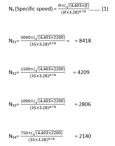
Q29 : The specific speed of an impeller is expressed as (N√Q) / H^0.75 , where N = speed, Q = flow in USGPM and H = head/stage in ft. Following are four impellers for double suction split-case pumps with their rated duties. What are their specific speeds (US units)?
| Impeller- 5HS12 | Impeller- 6HS17 | Impeller- 6HS22 | Impeller- 8HS26 |
| Q = 1110 US gpm | Q = 1760 US gpm | Q = 2200 US gpm | Q = 3170 US gpm |
| H = 72 ft. | H = 180 ft. | H = 295 ft. | H = 460 ft. |
| N = 1450 rpm | N = 1480 rpm | N = 1480 rpm | N = 1480 rpm |
- a)
Pump A 900 Pump B 975 Pump C 1263 Pump D 1954 - b)
Pump A 975 Pump B 1954 Pump C 1263 Pump D 840 - c)
Pump A 1954 Pump B 1263 Pump C 975 Pump D 840 - d)
Pump A 1263 Pump B 1954 Pump C 975 Pump D 900
Answer :
- c)
Pump A 1954 Pump B 1263 Pump C 975 Pump D 840
Mixed flow pump –high specific speed
Description :
For Impeller-5HS12 (A)
NS = N.√Q/H.75………(1)
Using (1) we get;
NS = 1954
For Impeller- 6HS17 (B)
NS = N.√Q/H.75………(2)
Using (2) we get;
NS = 1263
For Impeller- 6HS22 (C)
NS = N.√Q/H.75………(3)
Using (3) we get;
NS = 975
For Impeller- 8HS26 (D)
NS = N.√Q/H.75………(4)
Using (4) we get;
NS = 840
Q30 : Referring to Fraser-Sabini efficiency chart attached, what will be the efficiencies of the four pumps listed?
| Impeller- 5HS12 | Impeller- 6HS17 | Impeller- 6HS22 | Impeller- 8HS26 |
| Q = 1110 US gpm | Q = 1760 US gpm | Q = 2200 US gpm | Q = 3170 US gpm |
| H = 72 ft. | H = 180 ft. | H = 295 ft. | H = 460 ft. |
| N = 1450 rpm | N = 1480 rpm | N = 1480 rpm | N = 1480 rpm |
- a)
Pump A 84% Pump B 81% Pump C 80.5% Pump D 79% - b)
Pump A 83% Pump B 78% Pump C 84% Pump D 80% - c)
Pump A 82% Pump B 84% Pump C 83% Pump D 75% - d)
Pump A 81% Pump B 67% Pump C 85% Pump D 72%
Answer :
- a)
Pump A 84% Pump B 81% Pump C 80.5% Pump D 79%
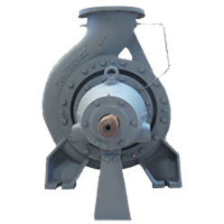
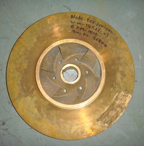
End suction model of Pumpsense make
Description :
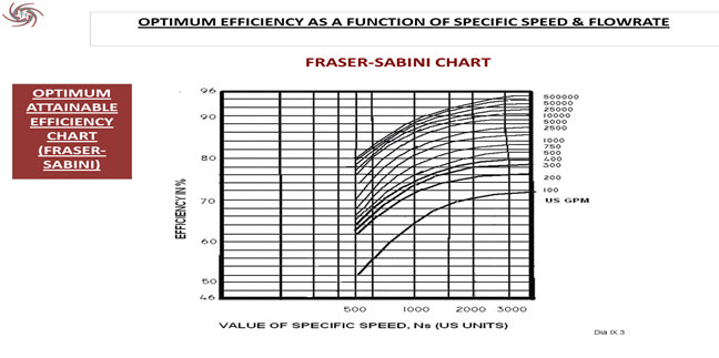
| Pump name | Flow rate | Sp. Speed | Efficiency |
|---|---|---|---|
| Pump A | 1110 | 1954 | 84% |
| Pump B | 1760 | 1263 | 80.8% |
| Pump C | 2200 | 975 | 80.5% |
| Pump D | 3170 | 840 | 79% |
Q31 : Suction specific speed is an indicator of the suction capability of a pump. It is also a measure of suction energy of the pump & its permissible range of operation. External fire pumps for ships (FiFi pumps) operate at a single duty point and the typical duties are as follows:
| Pump A | Pump B | Pump C | Pump D |
| Q = 2400 m3/hr. | Q = 1200 m3/hr. | Q = 600 m3/hr. | Q = 300 m3/hr. |
| H = 150 m | H = 140 m | H = 140 m | H = 140 m |
| N = 1800 rpm | N = 1800 rpm | N = 1800 rpm | N = 2100 rpm |
The suction specific speed (Nss) is given by
(N√Q)
/
((NPSHr)0.75)
where, N = speed in rpm, Q = flow/eye in US gpm and NPSHr is in ft.
Assuming that most commercially designed pumps achieve Nss = 9000 (US units), what would be the expected NPSHr of pumps A, B, C & D if all of them are double suction split-case single
- a)
Pump A 17.2 m Pump B 10.8 m Pump C 6.8 m Pump D 5.3 m - b)
Pump A 10.8 m Pump B 6.8 m Pump C 4.3 m Pump D 3.3 m - c)
Pump A 6.4 m Pump B 4.1 m Pump C 2.5 m Pump D 2.0 m - d)
Pump A 4.3 m Pump B 6.8 m Pump C 10.8 m Pump D 3.3 m
Answer :
- b)
Pump A 10.8 m Pump B 6.8 m Pump C 4.3 m Pump D 3.3 m
ESFX 250-300 - Ship’s external firefighting pump
Description :
NSS = N√Q / (NPSHr)0.75
NPSHr = ( (N√Q) / 9000 )1.33 ......... (1)
For Pump A
Using (1) we get
NPSHr = { (1800√((2400×4.403)/2)) / 9000 }1.33 = 35.48 ft = 10.8m
For Pump B
Using (1) we get
NPSHr = { (1800√((1200×4.403)/2)) / 9000 }1.33 = 22.3ft = 6.8m
For Pump C
Using (1) we get
NPSHr = { (1800√((600×4.403)/2)) / 9000 }1.33= 14.1 ft = 4.3m
For Pump D
Using (1) we get
NPSHr = { (2100√((300×4.403)/2)) / 9000 }1.33= 10.82ft = 3.3m
Q32 : A ship-owner is considering installation of two diesel engine driven external fire pumps on the ship deck. Pump duty and suction conditions are as follows: -
Rated capacity of each pump - 600 m3/hr
Rated head - 140 m
Static lift (minimum water level to pump center line) = 3.0 m
Total losses in the pipe line (strainer, bend, straight pipe, etc.) = 0.5 m
Vapor pressure = 0.6 m
Atmospheric pressure = 10.3 m
Available NPSH = (10.3 - 3.0 - 0.5 - 0.6) m = 6.2 m
The ship-owner wants to maintain a safety ratio of 1.2 (NPSHa/NPSHr) to prevent cavitation. What is the maximum speed at which he can run a) an end suction pump b) a double suction pump, considering that pumps operate at B.E.P for rated duties and that they have been designed for Nss = 9000 US units?
- a) End suction-2080 RPM & Double suction - 2080 RPM
- b) End suction-2080 RPM & Double suction - 1470 RPM
- c) End suction-1470 RPM & Double suction - 2080 RPM
- d) End suction-1677 RPM & Double suction - 2370 RPM
Answer :
- c) End suction-1470 RPM & Double suction - 2080 RPM
Clutch mounted Engine driven Ship’s external firefighting pump
Description :
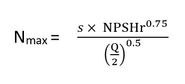
As per the question, NPSHr =NPSHa/1.2 = 6.2/1.2= 5.1667
Nmax = ( Nss×NPSHr 0.75 / Q0.5 ) for single suction
Nmax = { Nss×NPSHr 0.75 / (Q/2) }0.5 for double suction
End suction is a single suction design pump, so
Nmax = Nss×NPSHr 0.75 / (Q0.5)
Nmax = 9000× (5.16673.28)0.75 / (600×4.403) 0.5 = 1462 rpm
For double suction design pump
Nmax = 9000*(5.1667*3.28).75 / (600*4.403/2) 0.5 = 2068 rpm
Q33 : What is the NPSHa for the following system:
(Given, vapor pressure of water at pumping temperature is 0.5 m & suction vessel is open to atmospheric pressure.)
- a) 6.8 m
- b) 7.8 m
- c) 8.8 m
- d) 9.9 m
Answer :
- a) 6.8 m
NPSHr Test Bench at our existing factory
Description :
We know,
NPSHa = (atmospheric pressure head - total suction lift - vapour pressure head)
Where, atmospheric pressure head = 10.3 m
Total suction lift = (1.5+1.5) m
Vapour pressure head = 0.5 m
NPSHa = 10.3- (1.5+1.5) – 0.5 = 6.8m
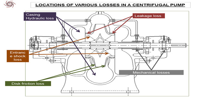
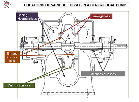
Q34 : The following figure shows various types of losses in a centrifugal pump. Please identify the labels with their positions & select the right option.
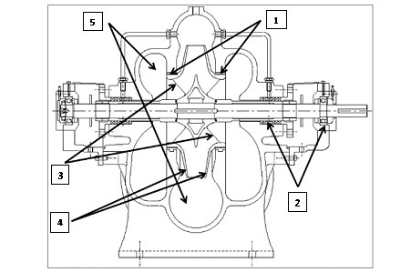
| Type of Losses | Labels |
|---|---|
| A) Entrance Shock losses | 1 |
| B) Mechanical losses | 2 |
| C) Leakage loses | 3 |
| D) Disk friction losses | 4 |
| E) Casing hydraulic losses | 5 |
- a)
A 1 B 5 C 2 D 3 E 4 - b)
A 1 B 5 C 3 D 2 E 4 - c)
A 4 B 2 C 1 D 3 E 5 - d)
A 4 B 1 C 5 D 2 E 3
Answer :
- c)
A 4 B 2 C 1 D 3 E 5

Centrifugal Split-case pump of Pumpsense make
Description :

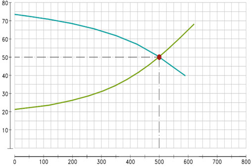
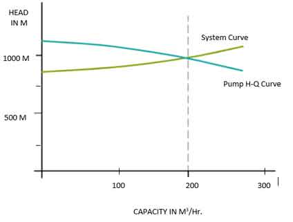
Q35 : Pump H-Q curve has been superimposed on the system curve in the figure below. Identify the head figures.
| Head Figures |
|---|
| A) Static Head |
| B) Friction head at duty point |
| C) Total Head at duty point |
| D) Friction head at 250 M3/Hr. |
| E) Total Head at 750 M3/Hr. |
- a)
A 28M B 22M C 50M D 80M E 9M - b)
A 22M B 28M C 9M D 50M E 80M - c)
A 22M B 28M C 50M D 7M E 85M - d)
A 80M B 28M C 50M D 7M E 22M
Answer :
- c)
A 22M B 28M C 50M D 7M E 85M
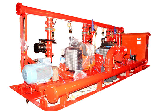
Our packaged firefighting unit: Ready for installation with system
Description :
So, static head = 22m (assuming zero pressure head)
Duty point head = 50m
Friction head = (50-22) = 28m
At 250 m3/hr friction head = (29-22) =7m
Now system curve total head = static head + friction head= 22+ KQ2
Or, 50 = 22 + K×5002 at operating point
Or, k = .00000112
At Q = 750 m3/hr
Total Head = 22+ K×7502 = 85m
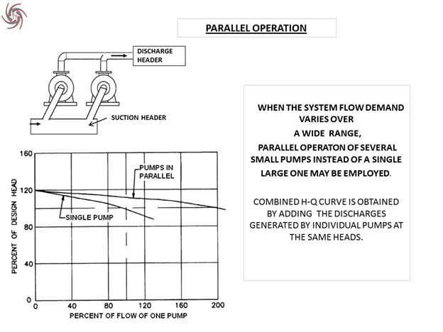
N.B: TO ACHIVE THIS HEAD WE REQUIRE 2 PUMPS OPERATING IN PARALLEL.
Q36 : The figure below represents curves for a pumping system. One would expect a system curve of this nature in the following systems.
| System | Options |
|---|---|
| Boiler Feed Pump | A) |
| Town Water Distribution | B) |
| Heat Exchanger | C) |
| Mine Dewatering | D) |
Answer :
- D)
Our Pump used for HVAC application
Description :
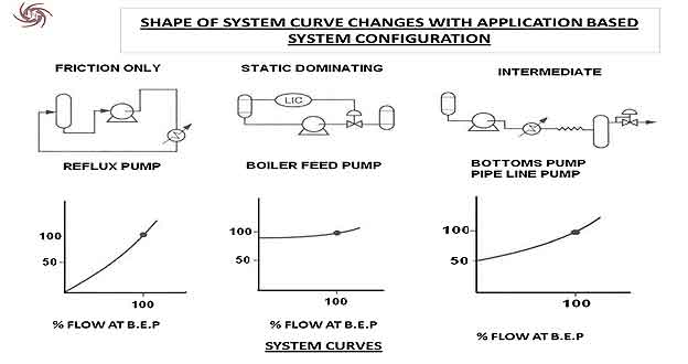
It is been clear that in boiler feed and mine dewatering pump the static head is dominating comparing to friction head. But in this question the head required is very high, which make the curve useful for mine dewatering.
N.B:- IN Town Water Distribution BOTH STATIC HEAD AND FRICTIONG HEAD are equivalently effective as the water supply pipe line length is long.
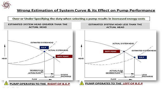
Q37 : If the system head is over estimated or if multiple margins are added to arrive at the pump total head, the Pump performance will be sub-optimal. Which of the following statement is not true for such a system?
- a) Pump will discharge more than the rated discharge
- b) Motor may get overloaded
- c) NPSHa may not be sufficient to suppress cavitation
- d) Axial thrust will increase
- e) Radial thrust will increase
Answer :
- d) Axial thrust will increase
Split-Case Pump
Description :
In the case of double suction type impeller, the axial thrust is always balanced as fluid is entering into the impeller from both sides thus balancing the axial thrust. But the radial thrust increase if the design operating point is changed.
Point A, B and C should be true.
To make it clear let’s take an example. Suppose, my static head is 20 m, and frictional head, is 10m (calculated by Darcy’s Equation).
Therefore, my system total head will be 30m.
But due to uncertainty of pipe inside area quality, the designer took a factor of 20% above friction head and considering the water level may fall, took a factor of 10% over static head.
So, the total system head is now = (10+ 10%of 10) + (20+ 20%of 20) = 35m.
Hence, the calculated operating point shift leftwards (but the actual opt point is on the right side of that point), (pumps operated at the right of the BEP), so it ensures more rated discharge, and a chance of motor getting overloaded and the chances of cavitation also increase.
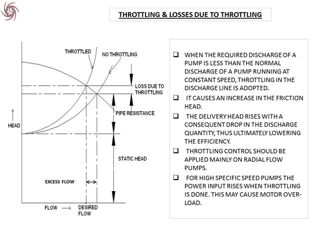
Q38 : When the required discharge of a pump is less than the normal discharge (valve fully open) and pump runs at a constant speed, throttling in the discharge line is sometimes adopted to reduce the flow. Throttling is an energy inefficient method of flow control but can be used with pumps using radial flow impellers. What is the main reason why throttling is not recommended for pumps with mixed flow or axial flow impellers?
- a) Excessive radial thrust load at part capacity
- b) Danger of pump operating in the unstable zone of H-Q characteristics
- c) Recirculation & part flow cavitation
- d) Power curve rises towards the shut-off & throttling may overload the motor
- e) All of the above
Answer :
- e) All of the above
Large End Suction Model
Description :
In axial flow and mixed flow type impeller the projected area on the shaft is large, though at part flow condition the increased pressure head is not high as radial flow pump. As, Force excreted on the shaft is directly proportional to the developed pressure and projected area, the total thrust is more (due to large projected area).So, point A) is true
In end suction axial flow pump, the overhung length of the shaft increases, so it becomes more unstable due to high shaft deflection in part flow (high radial thrust).Therefore, point B) is true.
And also in case of axial flow type impeller the eye diameter of the impeller is very large resulting in recirculation and part flow cavitation. So, point C) is true.
It also has rising Power curve characteristic towards shut-off because it has very sharp head rise near shut-off condition and poor efficiency. (Power is directly proportional to head and inversely proportional to efficiency) so point D) is true
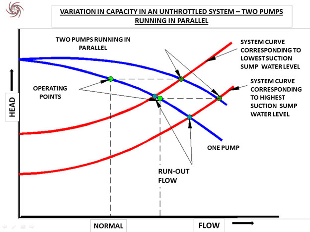
Q39 : The figure represents two identical pumps working in parallel in a water supply system. Water level in the suction sump varies between high & low limits. Please identify the labels in the diagram & put a tick mark against their right match:
| Item No. & Description of curve | Level |
|---|---|
| 1. H-Q curve of one pump | |
| 2. System characteristics corresponding to highest water level in suction sump | |
| 3. H-Q curve of two pumps running in parallel | |
| 4. System characteristics corresponding to lowest water level in suction sump | |
| 5. Run-out flow when only one pump operate with highest water level in the suction sump |
- a)
A 1 B 3 C 5 D 2 E 4 - b)
A 1 B 5 C 3 D 2 E 4 - c)
A 1 B 3 C 4 D 2 E 5 - d)
A 1 B 3 C 2 D 4 E 5
Answer :
- c)
A 1 B 3 C 4 D 2 E 5
API 610 OH2 – Centreline Mounted End-Suction Pump
Description :
Q40 : Air entrainment in the suction side of the pump can affect pump performance in diverse ways. Which of the following statements about air entrainment is not true for centrifugal pumps?
- a) Even with small amounts of air in the liquid the performance of the pump declines
- b) Open impellers handle entrained air or gas better than closed impellers due to clearance between the impeller & casing
- c) Air enters the pump suction through vortices formed in the suction sump, release of dissolved gas in the liquid, air leakage through valve stem packing or air deliberately injected into the pump
- d) Entrained air bubbles cushion the destructive effects of collapsing vapor bubbles when the pump is cavitating. Hence, air is sometimes injected deliberately, as a short-term measure, to prevent cavitation damage
- e) Entrained air reduces the NPSH required by the pump and therefore, improves the suction performance of the pump
Answer :
- e) Entrained air reduces the NPSH required by the pump and therefore, improves the suction performance of the pump
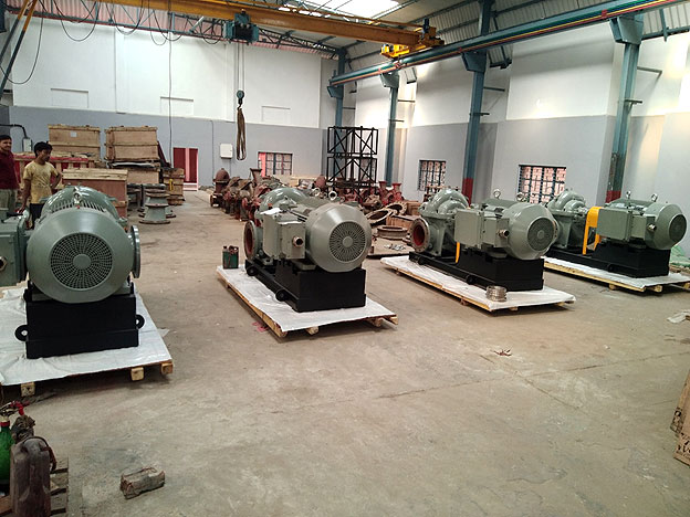
12HS13 – Pumps with motor set supplied to BHEL
Description :
Entrained air does not reduce the NPSH required by the pump but in turn it reduces the capacity of the pump. But, at the same time entrained air bubbles cushions the destructive effects of collapsing vapor bubbles.
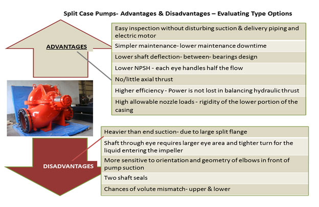
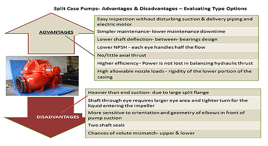
Q41 : The following is a mixed-up list of advantages of split case (SC) and end suction (ES) pumps. Each option contains some item nos. under the boxes. Please select the right option that correctly segregates the advantages for both the pump types :
- a) Easy inspection without disturbing suction & discharge piping and electric motor.
- b) Light weight & requires less floor space
- c) More sensitive to orientation and geometry of elbows in front of the pump suction
- d) Simpler maintenance, lower maintenance down time
- e) Lower NPSH due to double suction impeller
- f) Only one shaft seal
- g) No chances of volute mismatch between upper & lower cases
- h) No/little axial thrust
- i) High allowable nozzle loads - rigidity of the lower portion of the casing
- j) Higher efficiency, power is not lost in balancing axial thrust
- k) Larger inter-changeability because most pumps conform to international dimension standards for this class of pumps
- l) Lower first cost
- a)
SC ES a b c d e f h g i k j l - b)
SC ES a g b h c i d j e k f l - c)
SC ES a b c f d g e i h k j l - d)
SC ES a c b f d g e i h k j l
Answer :
- a)
SC ES a b c d e f h g i k j l
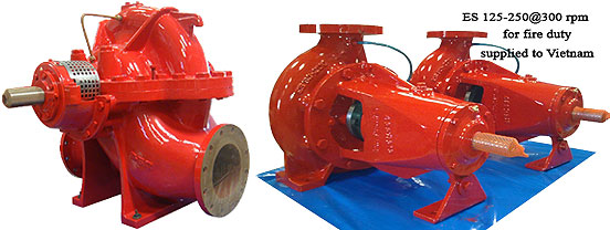
Splitcase & end suction pumps for firefighting applications
Description :
Q42 : You have a double volute axially split case pump 14″x16″ in size used for cold well duty of 5000 IGPM (1362 m3/hr.) and 150 ft (45.7 m) at 980 rpm. NPSH required by the pump at 980 rpm is 3.3 m and power absorbed is 200 kW (pump eff. 85%). You want to run the pump at 1480 rpm for a different application and the pump manufacturer has confirmed that the design speed of this pump is 1500 rpm. Please estimate the performance of the pump at 1480 rpm.
| Case A | Case B | Case C |
|---|---|---|
| Q = 1362 m3/hr | Q = 2043 m3/hr | Q = 2043 m3/hr |
| H = 68.6 m | H = 103 m | H = 68.6 m |
| Eff. = 85% | Eff. = 85% | Eff. = 85% |
| Power = 300kW | Power = 674.5kW | Power = 449.3kW |
| NPSHr = 7.5 m | NPSHr = 7.5 m | NPSHr = 3.3 m |
- a) Case A
- b) Case B
- c) Case C
- d) None of the above
Answer :
- b) Case B
Vertical Fire Pumps supplied to a shipyard in China
Description :
Flow calculation:
Q2 = Q1 × (N2/N1) = 1362 × (1480/980) = 2056 m3/hr
Head calculation:
H2 = H1 ×
(
N2
/
N1
)2 = 45.7 ×
(
1480
/
980
)2 = 104 m
Power calculation:
BKW =
Q(m3/hr) ×H(m) × specific gravity
/
3.67 × efficiency (%)
=
2056×104×1.00
/
3.67×85
= 685.74 KW
NPSHr calculation:
NPSHr2 = NPSHr1 ×
(
N2
/
N1
)X = 3.3 ×
(
1480
/
980
)2 = 7.52 m (ASSUMING X = 2)
N.B - FOR NPSH TEST the speed of rotation should lie within the range of 80% to 120% of the specified speed of rotation, provided that the rate of flow lies within 50% and 120% of the rate of flow corresponding to the maximum efficiency at the test speed of rotation. The value of X = 2 is applicable for this above mentioned condition. Now, if the pump operates near the cavitation limits or If the deviation of test speed from the specified speed is significant, the phenomena may be influenced by, for example, thermodynamic effects, variation of surface tensions or the differences in dissolved or occluded air content. In that case, X= 1.3 to 2.
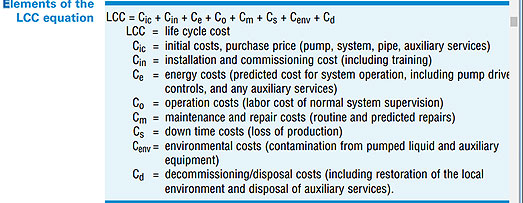
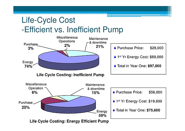
Q43 : Following are the typical cost items in a life cycle cost (LCC) analysis of a pumping system. Approximate % costs are presented as a separate list. Please try to match the cost items with your best estimate of percentage figures :
| Cost Heads | Cost Figures |
|---|---|
| 1. Maintenance Cost | a. 10% |
| 2. Operating Cost | b. 40% |
| 3. Downtime Cost | c. 25% |
| 4. Environmental Cost | d. 3% |
| 5. Installation Cost | e. 10% |
| 6. Pump Purchase Cost | f. 7% |
| 7. Energy Cost | g. 5% |
- a)
1 e 2 c 3 d 4 g 5 f 6 a 7 b - b)
1 a 2 c 3 d 4 b 5 e 6 g 7 h - c)
1 a 2 c 3 d 4 b 5 g 6 e 7 f - d)
1 c 2 e 3 d 4 g 5 f 6 a 7 b
Answer :
- d)
1 c 2 e 3 d 4 g 5 f 6 a 7 b
Vertical Split-case Cargo pump supplied in a large quantity for Mars Project
Description :

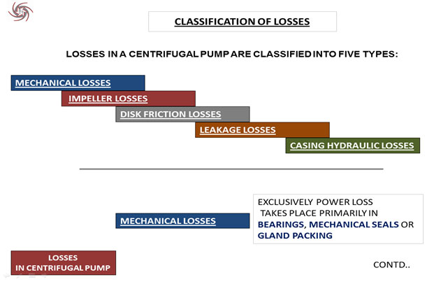
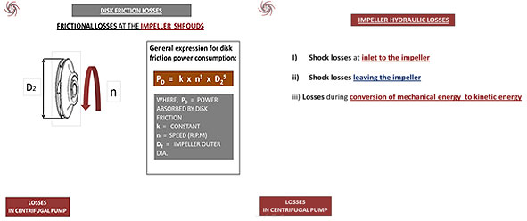
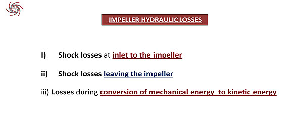
Q44 : Losses in a centrifugal pump can be classified, for convenience of analysis, into the following categories :-
- 1) Impeller hydraulic losses
- 2) Mechanical losses
- 3) Leakage losses
- 4) Disk friction losses
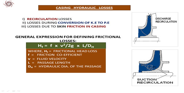
- 5) Casing hydraulic losses
The following is a list of locations within the pump. Please match the location with the type of losses.
| Location | Type of Losses |
|---|---|
| A) Impeller shroud faces | 1) Impeller hydraulic losses |
| B) Suction volute | 2) Mechanical losses |
| C) Impeller - wear ring gap | 3) Leakage loses |
| D) Gland Packing | 4) Disk friction losses |
| E) Vane passage | 5) Casing hydraulic losses |
- a)
A 1 B 3 C 5 D 2 E 4 - b)
A 1 B 5 C 3 D 2 E 4 - c)
A 4 B 5 C 3 D 2 E 1 - d)
A 4 B 1 C 5 D 2 E 3
Answer :
- c)
A 4 B 5 C 3 D 2 E 1
Vertical Split-case pump with motor
Description :
Q45 : The method followed in the field for a quick estimation of the minimum flow through the pump, to limit temperature rise to 80C (150F), is to calculate the power at B.E.P and consider 10% of the power (HP) in US gpm as the minimum flow (thermal) through the pump. For example, if the power absorbed is 100 HP (75 kW), the minimum flow will be estimated as 10 US gpm (2.3 m3/hr)
A multi-stage ring section pump is being used for the following duty :-
| Capacity | 108 m3/hr |
| Head | 500 m |
| Speed | 2950 rpm |
| Temperature | 900c |
| Specific gravity | 0.956 |
| Medium | De-mineralized water |
| Pump Efficiency | 72 % |
The user needs to plan for a minimum flow recirculation arrangement to prevent temperature rise beyond 80C. As a first approximation, what minimum flow should be considered for the recirculation arrangement?
- a) 19.5 m3/hr
- b) 6.0 m3/hr
- c) 10.8 m3/hr
- d) 4.4 m3/hr
Answer :
- b) 6.0 m3/hr
Customized model : Bottom suction-Top delivery end suction pump
Description :
Calculating power absorbed by the pump :
BKW =
Q(m3/hr) × H(m) × specific gravity
/
3.67 × efficiency (%)
=
108 × 500 × 1.00
/
3.67 × 72
= 204.35 KW = 272 HP (considering 1 kw = 0.75 hp)
Hence, minimum flow rate = 27.2 usgpm = 6.1 m3/hr
Q46 : For API 610 process pumps, the governing design philosophy is a very high level of mechanical reliability. This requires adopting design features which can lead to sub-optimal pump efficiency. The following is a list of special design features of API process pumps. Please identify one feature that definitely does not compromise pump efficiency.
The user needs to plan for a minimum flow recirculation arrangement to prevent temperature rise beyond 80C. As a first approximation, what minimum flow should be considered for the recirculation arrangement?
- a) Double volute casing construction
- b) Large shaft to reduce shaft deflection
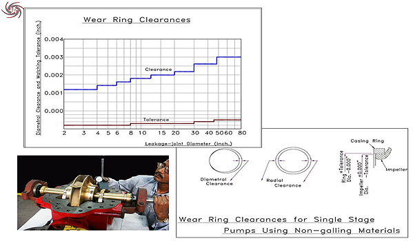
- c) Wear ring clearances as per API standards
- d) Large mechanical seals
- e) Centre-line mounted casing
Answer :
- e) Centre-line mounted casing
Centre-line mounted OH2 API 610 pump
Description :
All the other API 610 special design features consume power more than the general common design.
Q47 : Disk friction drag is a major component of pump losses in low specific speed pumps. The following are the duties of five split-case pumps - all pumps are single stage with double suction impellers. Pump D uses a double volute casing while all others have single volute casings :
| Pump A - 8x8-12 | Pump B - 6x8-14 | Pump C - 6x8-17 | Pump D - 6x8-21 |
| Q = 450 m3/hr | Q = 450 m3/hr | Q = 450 m3/hr | Q = 450 m3/hr |
| H = 22 m | H = 32 m | H = 55 m | H = 90 m |
| N = 1460 rpm | N = 1480 rpm | N = 1480 rpm | N = 1480 rpm |
Which pump is likely to have the highest disk friction loss as a proportion of the power input?
- a) A
- b) B
- c) C
- d) D
Answer :
- d) D
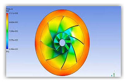
Design tool: CFD software simulation of pump performance & hydraulic losses
Description :
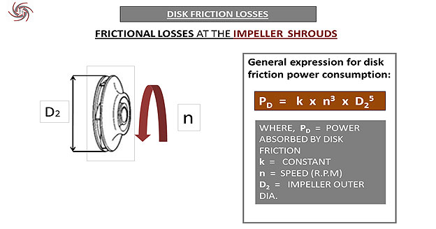
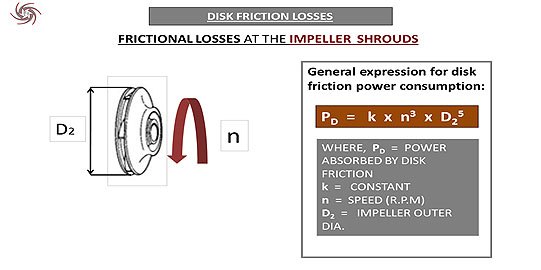
Disc Friction loss calculation
PD = k × n3 × D25 (For single entry impeller)
For pump A (Double entry)
PD = k × n3 × D25 = 2 × K × 14603 × ( 12 / 12 )5 = 0.6 × 10¹⁰ K units
For pump B (Double entry)
PD = k × n3 × D25 = 2 × K × 14803 × ( 14 / 12 )5 = 1.40 × 10¹⁰ K units
For pump C (Double entry)
PD = k × n3 × D25 = 2 × K × 14803 × ( 17 / 12 )5 = 3.7 × 10¹⁰ K units
For pump D (Double entry)
PD = k × n3 × D25 = 2 × K × 14803 × ( 21 / 12 )5 = 10.6 × 10¹⁰ K units
N.B : To reduce disk friction loss, one can perform high surface finish machining operation near the impeller outlet, as the outlet area causes more disk friction loss (AS PD is proportional to D25).
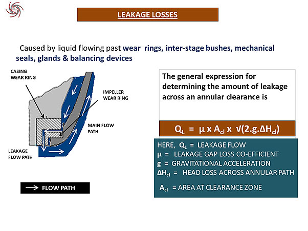
Q48 : Leakage loss in a single stage centrifugal pump with shrouded impeller takes place through the clearances between the impeller and casing wear rings. Leakage loss is a function of the pump specific speed. Lower efficiency of low specific speed centrifugal pumps is due, mainly, to high leakage and disk friction losses. Which of the following statements regarding leakage losses is definitely not true?
- a) Drop in efficiency due to increased leakage losses can be corrected by restoring wear ring clearances
- b) Use of compatible impeller and wear ring materials with adequate anti-galling properties allow smaller wear ring clearances and reduce leakage losses
- c) Leakage loss depends on the pressure differential between the suction & delivery side of wear ring and on wear ring clearance. Width of the wear ring does not have any effect on the leakage losses
- d) Increased shaft stiffness reduces the shaft deflection at the impeller and allows lower clearance between impeller & wear ring and this reduces leakage losses
Answer :
- c) Leakage loss depends on the pressure differential between the suction & delivery side of wear ring and on wear ring clearance. Width of the wear ring does not have any effect on the leakage losses
Split-case marine pump with side suction and top discharge flanges from our SFM range
Description :
With increase in width of the wear rings, the resistance to water flow between the clearance of wear rings increase, which in turn decreases the leakage.

Mathematically, leakage gap loss co-efficient decreases so QL DECREASES
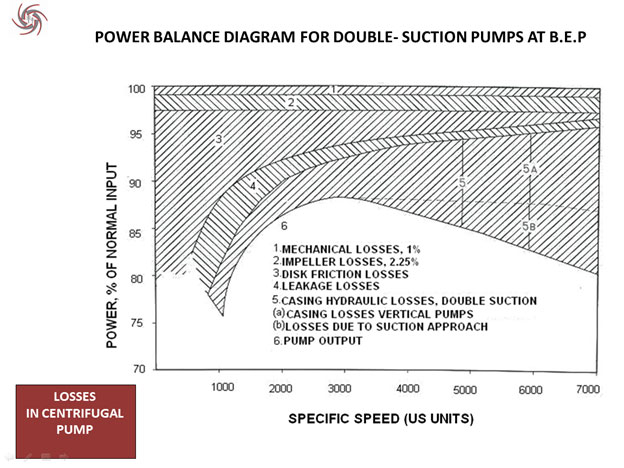
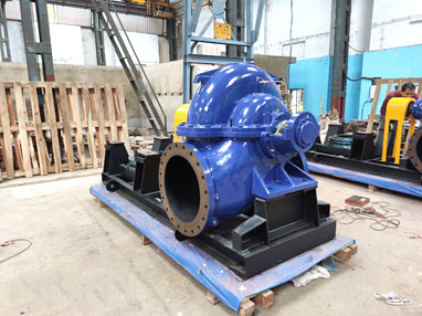
Q49 : Power balance diagram and specific speed vs. efficiency charts suggest that for a required combination of capacity and head, a pump of optimum efficiency can be obtained if the operating speed is selected such that the pump specific speed is close to 2500 US units. It is to be noted that suction condition (NPSHa, limiting suction specific speed, etc.) often determine the pump operating speed & does not allow using the optimum specific speed of 2500 US units mentioned above. A refinery is considering installation of cooling water pumps of the following description :-
| Type | Vertical shaft axially split-case |
| Capacity | 2200 m3/hr |
| Head | 35 m |
| Suction | 3.0 m positive head on the suction side |
| Supply System | 50 Hz |
The refinery can choose from operating speeds of 3000 rpm, 1500 rpm, 1000 rpm or 750 rpm. Which operating speed is likely to offer the optimum pump suction performance with efficiency?
- a) 1500 RPM
- b) 1000 RPM
- c) 750 RPM
- d) 3000 RPM
Answer :
- b) 1000 RPM
Two of the 16 ESF (marine fire-fighting) pumps supplied to a shipbuilder in Hong Kong
Description :
Either 1000 RPM or 750 RPM will give the maximum efficiency.
Now, NPSHA= 10.3- 0.6+3- losses = (12.7- losses) m
Now considering suction sp speed (s) = 10000 (metric)
NPSHr for 1000 RPM = 5m
NPSHr for 750 rpm =3.37m
So NPSH MARGIN is higher for 750 RPM, however, the pump dimension becomes very high.
So we choose 1000 RPM.
Q50 : Lower the specific speed of the pump, higher is the ratio of impeller outlet diameters (D2) to impeller inlet or eye diameter (D1). Lower the D2/D1 ratio, lower is the allowable range of operation to prevent recirculation, low flow cavitation, vibration & radial loading. Out of the three options listed below which pump will permit the widest range of head-capacity operation.
| Pump A | Pump B | Pump C |
|---|---|---|
| Q = 2200 m3/hr | Q = 2200 m3/hr | Q = 2200 m3/hr |
| H = 35 m | H = 35 m | H = 35 m |
| N = 1480 rpm | N = 980 rpm | N = 740 rpm |
| Type - Axially split-case | Type - Axially split-case | Type - Axially split-case |
- a) Pump A
- b) Pump B
- c) Pump C
- d) Insufficient data
Answer :
- c) Pump C
Huge split-case 16HS21 ready for shipment
Description :
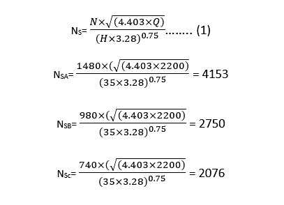
As a lower specific speed pump has a higher D2/D1 ratio and a wide optimum zone, pump C will serve our purpose most appropriately.